The Timing System @ PITZ
The aim of the Timing System at PITZ is to synchronize the operation of
- the LLRF-Systems of gun and booster cavity
- the Laser System
and the Diagnostic Elements (like ADC readout for BPM's, Faraday Cups and ICT's, Camera Systems etc.).
The major components are:
- the RF Master Oscillator
- the Repetition Rate Generator Module
- the Clock Generator Module
- Clock Repeater boards
- several Delay Timer Modules
- and some 8-Channel Delay Boards were it is necessary.
The RF Master Oscillator provides a set of signals with different frequencies for the synchronization of the sub-systems of the PITZ-Linac. These frequencies have a fixed phase relationship with respect to each other. The list of these frequencies and there usage can be found here. All signals require a very low phase jitter in the order of a few hundred femtoseconds (10-12s).
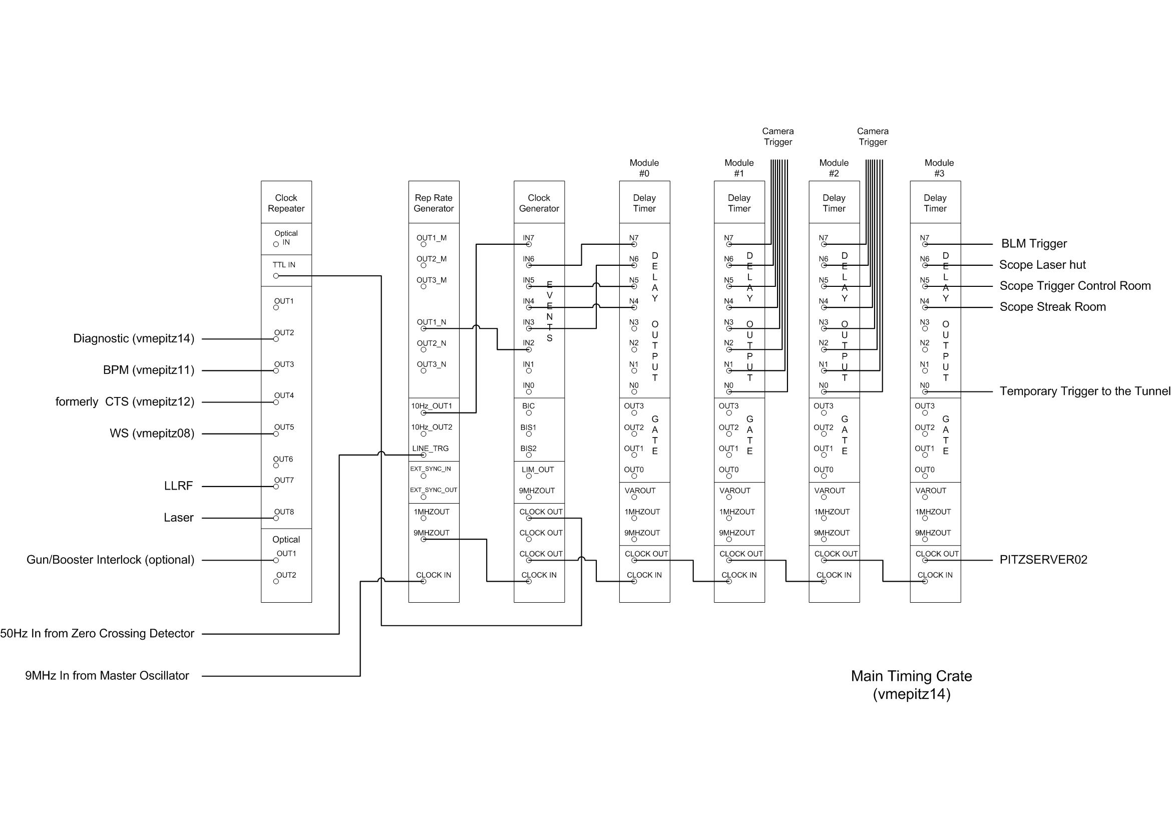
The Repetition Rate Generator gets his trigger from the 50Hz line frequency. Dividing the line frequency by 5 a 10Hz-Signal is provided which defines the maximum bunch repetition rate. Programmable divider allow for repetition periods from 100ms up to 1000s. Synchronization with the line suppresses the common noise for all systems. The trigger output from the repetition rate generator is delivered to the Clock Generator Module.
It can receive up to eight input signals. The Clock Generator outputs encoded Events on the 9MHz signal. It uses bi-phase marked code (BMC) for event encoding. The encoded clock signal is distributed to all Delay Timer Modules within the system. To deliver the signal over long distances (up to 40m) to the sub-systems like Laser and RF-Stations a Clock Repeater Module is used. It can send and/or receive signals either in optical or electrical input/output. For the clock input either the optical or the electrical input has to be used.
The Delay Timer Modules receiving the clock signal are located in different sub-systems at different places: at the Laser, in the Klystron hall to the RF-Stations and on the diagnostic racks. An on-board event encoder/decoder detects the incoming clock and provides up to 8 delayed trigger output pulses or 4 trigger gates where the delay and the width of the output pulse is controlled by a pair of trigger signals. While the first trigger pulse starts the gate the second one stops it therefore controlling delay and width of that gate. Beside gate and trigger output the Delay Timer Module delivers the recovered 9MHz-signal, a 1MHz-signal and a signal with variable frequency. This frequency can be programmed to be 9MHz, 4.5MHz, 2.25MHz or 1MHz. These signals are foreseen for the ADC Sampling Clock.
The Repetition Rate Generator, the Clock Generator and the Delay Timer Module are based on the same hardware using the IP Module IP_UNI_XILINX.
To do fine tuning of the ADC Sampling Clock a 8-Channel Digital Delay Board is used. The delay stepping can be either 0.5ns or 4ns depending on the delay line used on board. The number of steps is 256.
The following picture shows the configuration within the the Main Timing Crate.
