Clock Generator
Description
The design of the Clock Generator Module is based on the IP-UNI-XILINX board.
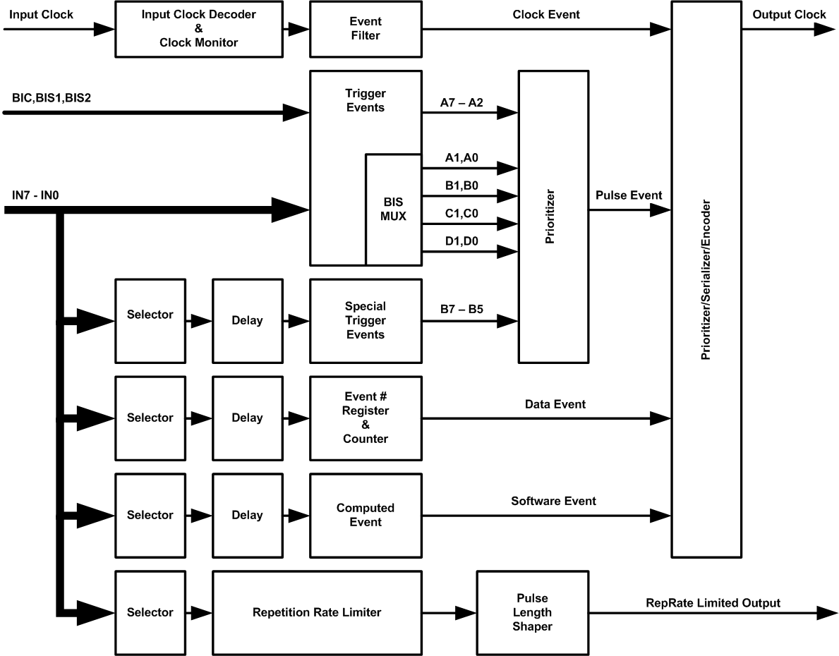
The task of the Clock Generator is to create 8-bit event messages on a serial output clock line with a start bit preceding and a parity bit following. For the transmission Bi-Phase Marked Code is used. These messages are received and decoded by Delay Timer Units for the synchronization of devices along the FLASH facility.
There are four sources of an event:
- a trigger at the Inputs IN7-IN0 (pulse event)
- incoming events on the clock input (if more than one clock generator exists in the system)
- event number data
- and software generated events (synchronized with an external trigger).
The events are prioritized as they are listed above from highest to lowest priority. The simplified block scheme below illustrates how the different events are processed.
A 32-bit data word may be send as a set of ten events or a computed event will be generated by writing to a single register. Recently only a32-bit event number is send to the Delay Timers. In later versions more data types could be send to transmit generalized status information to other devices. The transmission may be synchronized by external signals from the inputs In7-In0.
Signals from the beam inhibit system (BIC, BIS1, BIS2) are used to generate special events defining the running mode of the accelerator.
A special output signal with repetition rate limitation is generated. It may be used to protect the system and prevent damages due to too high trigger rate at the pulsed inputs. Which trigger signal is used for repetition rate limitation can be set by setting a register as well as the maximum allowed output cycle time.
The list of events used at PITZ can be found here.
Specification
- IP Interface Logic
Bi-phase marked code (BMC) Encoder for events from 8 trigger inputs
Bi-phase marked code (BMC) Decoder for incoming clock events
- 32-bit Event Number Counter
- Computed Event Generator
- Repetition Rate Limiter
Simplified Block Scheme
Documents
A more general and detailed description of the module can be found here.
