CONTENTS
Introduction
The CMS Beam Conditions and Radiation Monitoring System, BRM, measures the accumulated dose near or within all CMS sub-detectors, support beam tuning and protect the CMS detector from adverse beam conditions. It is composed of different sub-systems monitoring the beam halo conditions and collision products with different time resolution.
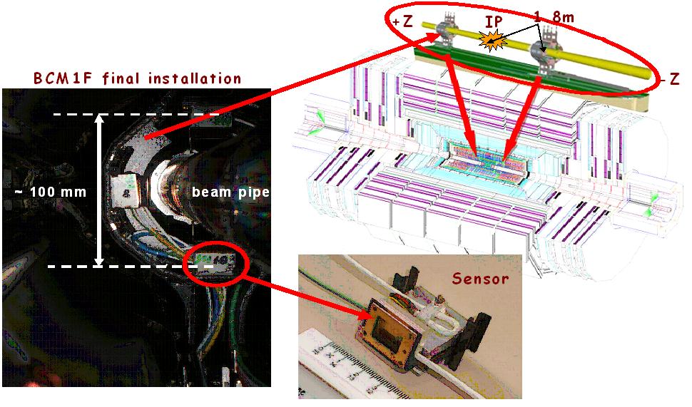
BCM1F is a subsystem of BRM, and is designed for fast flux monitoring measuring bunch-by-bunch both beam halo and collision products. BCM1F is located inside the CMS pixel detector volume close to the beam-pipe. It uses sCVD diamond sensors and radiation hard front-end electronics, along with an analog optical readout of the signals.

BCM1F and neighbouring detectors
The figure is obsolete since the BSC and CASTOR were dismantled in 2011. A BHC system was installed.
BCM1F eta (pseudorapidity)
Diamond and metallization size
The sensors are single-crystal chemical vapour deposition (sCVD) diamonds with a size of 5 * 5 * 0.5 mm^3. (Actual thickness ranges from 0.40 - 0.55 mm.) They are metallized on both sides (The metallization is 4.7 * 4.7mm )and operate as solid state ionization chambers.
Readout chain and data acquisition
Charge-sensitive, radiation-hard amplifier ASICs of the type JK16 collect the induced charge and shape proportional signals. Using an optical driver, they are transmitted as analogue optical signals to a service room where they are converted back to electrical signals in the optical receiver. The analogue signals are then fanned-out into a discriminator and to an analog-to-digital converter (ADC). The latter one samples the waveform of the signals to obtain a precise digital image. The discriminator supplies logical signals to a scaler and to a time-to-digital converter, TDC. Data acquired by these three readout devices are processed immediately. Relevant results are displayed in the control room and passed on to the central CMS data acquisition. Raw data are stored permanently on disk for offline analysis.
Signal conversion into light (more detailed info from Wolfgang Lange)
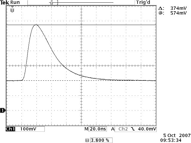
The signal charge from the diamond is collected in a charge sensitive preamplifier with shaper:

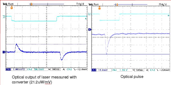
This signal is AC-coupled to the input of a laser driver circuit (this circuit supplies a DC-bias level and modulates the signal onto this quiescent level). The output of the laser driver is directly connected to a laser diode. The laser diode has a fibre connection (mono mode fibre) with an optical connector ('pig tail'). See pictures:

From this connector the signal is routed via several fibers and interconnections to the optical receiver module (in counting room S1) where it is re-converted into an electrical signal.