Eight Channel Programmable Delay Timer
Description
The design of the 8-channel delay timer is based on the IP-UNI-XILINX board.
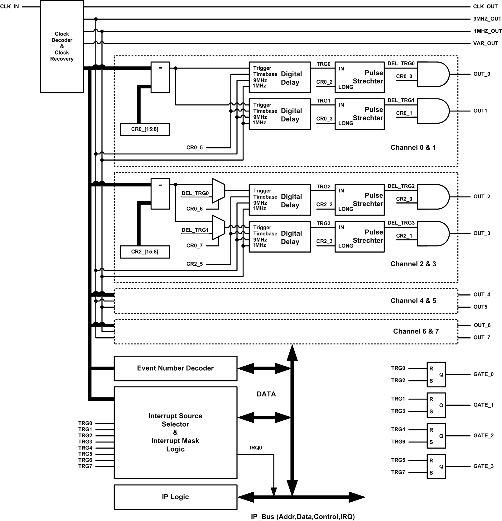
The incoming event on the Clock Input is decoded and parallelized as well as the clock recovery takes place. The event data are compared with the contents of the Event Control Register (ECR). In case of matching a programmable 16-bit digital delay line is triggered whereas two adjacent channels are triggered by the same event. The delay ranges from 0-7.2ms or 0-65.5ms depending on the timebase (110ns/1us) chosen. The output pulse duration is set by a pulse stretcher to be either 1us or 10us. The two output channels can be separately enabled or disabled. For very long delays two channels can be daisy chained. The pairs are Ch0-Ch2, Ch1-Ch3, Ch4-Ch6 and Ch5-Ch7.
A set of four R-S-Flip Flops form four output gates. While the first channel sets the FF the second one resets it thus forming a gate with variable delay and length. The pairing is like above.
The module serves three different clock outputs. Two of them have fixed frequencies (1MHz, 9MHz) on the third output the frequency can be varied (9MHZ, 4.5MHz, 2.25MHz, 1MHz).
The module is able to generate interrupts. The source of the interrupt can be either an event itself or a triggered output with delay. The event selection for interrupts is done in four registers. Each interrupt source can be enabled separately by a mask register. Pending interrupts can be cleared also separately.
A special set of event values has been reserved for transmission of 32-bit data over the clock line. In the current design a unique event number is received and decoded. With this event number data can be tagged.
Specification
- Event Decoder with clock recovery
- Two Clock outputs at 9MHz and 1MHZ fixed
- One variable Clock output (9MHZ, 4.5MHz, 2.25MHz, 1MHz)
- Eight Outputs with programmable delay and daisy chain option (16bit delay register)
- Time resolution 110ns or 1us (time base control)
- Pulse length control (either 110ns or 1us output)
- Pulse Output Enable
- Four Gate Outputs with programmable delay and width
- Event Number Decoder and Storage
- Interrupt logic with interrupt source selection
- IP-Interface Logic
Block Scheme
